|
Out-of-Plane Buckling Analysis of Curved Beams Considering Rotatory Inertia Using DQM |
|
Ki-jun Kang Department of Mechanical Engineering, Hoseo University |
|
미분구적법(DQM)을 이용 회전관성을 고려한 곡선 보의 외평면 좌굴해석 |
|
강기준 호서대학교 공과대학 기계공학부 |
|
Abstract Curved beams are increasingly used in buildings, vehicles, ships, and aircraft, which has resulted in considerable effort towards developing an accurate method for analyzing the dynamic behavior of such structures. The stability behavior of elastic curved beams has been the subject of many investigations. Solutions to the relevant differential equations have traditionally been obtained by the standard finite difference or finite element methods. However, these techniques require a great deal of computer time for a large number of discrete nodes with conditions of complex geometry and loading. One efficient procedure for the solution of partial differential equations is the differential quadrature method (DQM). This method has been applied to many cases to overcome the difficulties of complex algorithms and high storage requirements for complex geometry and loading conditions. Out-of-plane buckling of curved beams with rotatory inertia were analyzed using DQM under uniformly distributed radial loads. Critical loads were calculated for the member with various parameter ratios, boundary conditions, and opening angles. The results were compared with exact results from other methods for available cases. The DQM used only a limited number of grid points and shows very good agreement with the exact results (less than 0.3% error). New results according to diverse variation are also suggested, which show important roles in the buckling behavior of curved beams and can be used for comparisons with other numerical solutions or experimental test data. |
|
요 약 빌딩, 자동차, 선박, 항공기 등에서의 곡선보 사용 증가가 이러한 구조물의 동적거동해석에 필요한 정확한 해법 발전에 괄목할 만한 기여를 해왔다. 탄성곡선보의 안정성거동은 많은 연구자들의 한 과제분야였다. 전통적으로 미분방정식의 해법은 유한치분법이나 유한요소법으로 해결해왔다. 이러한 방법들은 복잡한 기하학적 구조 및 하중에 따른 격자점의 증가로 많은 컴퓨팅시간을 요구한다. 편미분방정식의 해를 구하기 위한 효율적인 방법 중의 하나는 미분구적법이다. 복잡한 기하학적 구조 및 하중 은 컴퓨터 용량을 과도하게 사용할 뿐만 아니라, 복합알고리즘 프로그램을 어렵게 해 이를 극복하기위하여 미분구적법(DQM)이 많은 분야에 적용되어왔다. DQM을 이용하여 곡선 보의 회전관성을 고려한 외 평면 좌굴을 등분포하중 하에서 해석하였다. 다양한 매개변수 비, 경계조건, 그리고 열림 각에 따른 임계하중을 계산하였다. DQM 결과는 활용 가능한 다른 엄밀해와 비교하였다. DQM은 적은 격자점을 사용하고도 엄밀해 결과와 일치함을 보여주었다 (0.3% 미만). 다양한 변경에 따른 새로운 결과가 또한 제시 되였고, 그 결과는 곡선 보의 좌굴거동에 중요한 역할을 보여주었고, 다른 수치해석결과 혹은 실험결과비교에 사용될 수 있다.
Keywords : Buckling, DQM, New Result, Out-of-Plane, Rotatory Inertia, Uniformly Distributed Radial Load |
![]()
1. Introduction
The increasing use of curved beams in buildings, vehicles, ships, and aircraft has results in considerable effort being directed toward developing an accurate method for analyzing the dynamic behavior of such structures. The stability behavior of elastic curved beams has been the subject of a large number of investigations. Solutions of the relevant differential equations have traditionally been obtained by the standard finite difference or finite element methods. These techniques require a great deal of computer time as the number of discrete nodes becomes relatively large under conditions of complex geometry and loading. In a large number of cases, the moderately accurate solution which can be calculated rapidly is desired at only a few points in the physical domain. However, in order to get results with even only limited accuracy at or near a point of interest for a reasonably complicated problem, solutions often have dependence of the accuracy and stability of the mentioned methods on the nature and refinement of the discretization of the domain.
Neglecting the warping effect, the elastic stability of ring segments with a thrust or a pull directed along the chord was studied by Ojalvo et al.[1]. Vlasov[2] has obtained closed-form solutions for the stability of an arch under the in-plane bending and uniformly distributed radial loads. Both the effects of axial stress and warping were included by Cheney[3] in the buckling analysis of rings. Yoo and Pfeiffer[4] derived the flexural-torsional buckling equations which were based on a different derivation of the total potential. Papangelis and Trahair[5] also derived nonlinear expressions for the axial and shear strains of doubly symmetric curved beams form the consideration of the deformed geometry. Trahair and Papangelis[7] developed the out-of-plane stability of arches in which the arches were loaded only in the plane of curvature. Yang and Kuo[8] presented a set of four differential equations derived from the principle of virtual displacements for curved beams with the web lying normal to the plane of curvature. In addition, different approaches were also presented by Kuo and Yang[9] to support their studies treating a curved beam as the composition of an infinite number of infinitesimal straight beams. Recently, Kang and Yoo[10] presented a theoretical study on the buckling of thin-walled curved beams with the derivation of stability equations, and Pi et al.[11] investigated the effect of prebuckling deformations on flexural-torsional buckling of arches. Kang and Han[12] studied buckling of arches without rotatory inertia using the DQM.
A rather efficient alternate procedure for the solution of partial differential equations is the method of differential quadrature which was introduced by Bellman and Casti[13]. This method is used in the present work to analyze the out-of-plane buckling of curved beams including the effect of rotatory inertia under uniformly distributed radial loads. The critical loads are calculated for the beams, and results are compared with existing exact solutions where available.
2. Theoretical Method
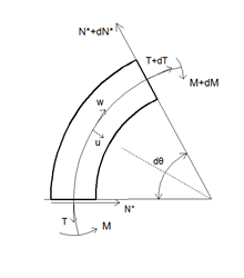
The uniform curved beam considered is shown in Fig. 1 subjected to uniformly distributed radial load ![]() per unit of circumferential length. A point on the centroidal axis is defined by the angle
per unit of circumferential length. A point on the centroidal axis is defined by the angle ![]() , measured from the left support, and the radius of the centroidal axis is
, measured from the left support, and the radius of the centroidal axis is ![]() . The tangential and radial displacements of the arch axis are
. The tangential and radial displacements of the arch axis are ![]() and
and ![]() , respectively.
, respectively. ![]() and
and ![]() are the displacement at right angles to the plane of the beam and the angular rotation of a cross section, respectively. These displacements are considered to be positive in the directions indicated. From Fig. 1, the compressive force
are the displacement at right angles to the plane of the beam and the angular rotation of a cross section, respectively. These displacements are considered to be positive in the directions indicated. From Fig. 1, the compressive force ![]() in the beam is
in the beam is ![]() . This compressive force may cause buckling of the beam either in its plane or out of its plane. The corresponding buckling equations can be deduced from the coupled twist-bending vibration equations suggested by Timoshenko and Gere[6] in investigating the torsional buckling of open section columns. His procedure is merely to replace the external load term by a fictitious load whose intensity is the load causing buckling times the appropriate 'curvature' term. The equations for the free vibrations of curved beams neglecting warping are:
. This compressive force may cause buckling of the beam either in its plane or out of its plane. The corresponding buckling equations can be deduced from the coupled twist-bending vibration equations suggested by Timoshenko and Gere[6] in investigating the torsional buckling of open section columns. His procedure is merely to replace the external load term by a fictitious load whose intensity is the load causing buckling times the appropriate 'curvature' term. The equations for the free vibrations of curved beams neglecting warping are:
![]() (1)
(1)
![]() (2)
(2)
![]() (3)
(3)
Where ![]() and
and ![]() are the bending moment, the torsional moment, and the transverse shear, respectively. Here
are the bending moment, the torsional moment, and the transverse shear, respectively. Here![]() is the mass per unit length,
is the mass per unit length, ![]() is the cross sectional area,
is the cross sectional area, ![]() is the time, and
is the time, and![]() is the polar moment of inertia of the cross section.
is the polar moment of inertia of the cross section.
Differentiating equation (1) once with respect to ![]() and substituting equation (3) in the resulting equation give
and substituting equation (3) in the resulting equation give
![]() (4)
(4)
The equation of the elastic curve of transversely loaded curved beam without warping is obtained by expressing curvature and twist in terms of deflection ![]() and the angle of rotation
and the angle of rotation ![]() . This yields (Tan and Shore[14])
. This yields (Tan and Shore[14])
![]() (5)
(5)
![]() (6)
(6)
Where ![]() is Young's modulus of elasticity,
is Young's modulus of elasticity, ![]() is the moment of inertia of cross section,
is the moment of inertia of cross section, ![]() is the shear modulus, and
is the shear modulus, and ![]() is the torsion constant. Here
is the torsion constant. Here ![]() and
and ![]() are the flexural rigidity and the torsional rigidity, respectively.
are the flexural rigidity and the torsional rigidity, respectively.
Substituting equations (5) and (6) into equations (2) and (4) leads in the following the differential equations of out-of-plane vibration of curved beams:
![]()
![]()
![]() (7)
(7)
![]()
![]() (8)
(8)
in which each prime denotes one differentiation with respect to the dimensionless distance coordinate ![]() , in which
, in which ![]() is the opening angle of the member.
is the opening angle of the member.
On the basis of Timoshenko and Gere[6], the buckling equations may be deduced from the equation by formally replace the inertial terms suggested by Wah[15]
![]() (9)
(9)
![]() (10)
(10)
![]() (11)
(11)
From equations (10) and (11), ![]() is the slope at right angle to the plane of the beam, and
is the slope at right angle to the plane of the beam, and ![]() is the rate of change of angle of twist. Thus, the following set of differential equations can be obtained for the buckling of a curved beam under uniformly distributed radial loads.
is the rate of change of angle of twist. Thus, the following set of differential equations can be obtained for the buckling of a curved beam under uniformly distributed radial loads.
![]()
![]() (12)
(12)
![]()
![]() (13)
(13)
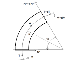
Fig. 2. Forces on a curved beam
or ![]()
![]() (14)
(14)
![]()
![]() (15)
(15)
Ojalvo et al.[1] studied the elastic stability of ring segments neglecting rotatory inertia in the equation (13).
The boundary conditions for both ends clamped, both ends simply supported, and mixed clamped-simply supported ends are, respectively,
![]() at X=0 and 1 (16)
at X=0 and 1 (16)
![]() at X=0 and 1 (17)
at X=0 and 1 (17)
![]() at X=0,
at X=0,
![]() at X=1 (18)
at X=1 (18)
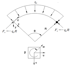
Fig. 1. Coordinate system with radial loads

3. Differential Quadrature Method
A rather efficient alternate procedure for the solution of partial differential equations is the method of differential quadrature which was introduced by Bellman and Casti[13]. Jang et al.[16] applied the DQM for the first time to static analysis of structural components. Recently, Kang and Kim[17], and Kang and Park[18] studied the vibration and the buckling analysis of asymmetric curved beams using DQM, respectively.
The application of the differential quadrature method to a partial differential equation can be expressed as follows:
![]() for
for ![]() (19)
(19)
where L denotes a differential operator, ![]() are the discrete points considered in the domain,
are the discrete points considered in the domain, ![]() are the row vectors of the
are the row vectors of the ![]() values,
values, ![]() are the function values at these points,
are the function values at these points, ![]() are the weighting coefficients attached to these function values, and N denotes the number of discrete points in the domain. This equation, thus, can be expressed as the derivatives of a function at a discrete point in terms of the function values at all discrete points in the variable domain.
are the weighting coefficients attached to these function values, and N denotes the number of discrete points in the domain. This equation, thus, can be expressed as the derivatives of a function at a discrete point in terms of the function values at all discrete points in the variable domain.
The general form of the function ![]() is taken as
is taken as
![]() for
for ![]() (20)
(20)
If the differential operator L represents an ![]() derivative, then
derivative, then
![]()
for![]() (21)
(21)
This expression represents N sets of N linear algebraic equations for the weighting coefficients, ![]() .
.
4. Numerical Application
The DQM is applied to the determination of the out-of-plane buckling of the beams. The differential quadrature approximations of the governing equations and boundary conditions are shown.
Applying the differential quadrature method to equations (14) and (15) gives
![]()
![]() (22)
(22)
![]()
![]() (23)
(23)
where ![]() and
and![]() are the weighting coefficients for the second- and fourth-order derivatives, respectively, along the dimensionless axis.
are the weighting coefficients for the second- and fourth-order derivatives, respectively, along the dimensionless axis.
The boundary conditions for clamped ends, given by equation (16), can be expressed in differential quadrature form as follows:
![]() at
at ![]()
![]() at
at ![]()
![]() at
at ![]()
![]() at
at ![]()
![]() at
at![]()
![]() at
at![]() (24)
(24)
where ![]() is the weighting coefficients for the first- order derivatives. Here,
is the weighting coefficients for the first- order derivatives. Here, ![]() denotes a very small distance measured along the dimensionless axis from the boundary ends. In their work on the application of DQM to the static analysis of beams and plates, Jang et al.[16] proposed the so-called
denotes a very small distance measured along the dimensionless axis from the boundary ends. In their work on the application of DQM to the static analysis of beams and plates, Jang et al.[16] proposed the so-called ![]() -technique wherein adjacent to the boundary points of the differential quadrature grid points chosen at a small distance. This
-technique wherein adjacent to the boundary points of the differential quadrature grid points chosen at a small distance. This ![]() approach is used to apply more than one boundary conditions at a given station.
approach is used to apply more than one boundary conditions at a given station.
The boundary conditions for simply supported ends, given by equation (17), can be expressed in differential quadrature form as follows:
![]() at
at ![]()
![]() at
at ![]()
![]() at
at ![]()
![]() at
at ![]()
![]() at
at![]()
![]() at
at![]() (25)
(25)
Similarly, the boundary conditions for one clamped and one simply supported end, given by equation (18), can be expressed in differential quadrature form as
![]() at
at ![]()
![]() at
at ![]()
![]() at
at ![]()
![]() at
at ![]()
![]() at
at![]()
![]() at
at![]() (26)
(26)
This set of equations together with the appropriate boundary conditions can be solved for the out-of-plane buckling of the beams.
5. Numerical Results and
Comparisons
The out-of-plane buckling parameter ![]() subjected to uniformly distributed radial loads is calculated by the DQM and is presented together with existing exact solutions by Timoshenko and Gere[6]. The value
subjected to uniformly distributed radial loads is calculated by the DQM and is presented together with existing exact solutions by Timoshenko and Gere[6]. The value ![]() is evaluated for the case of various end conditions, opening angles, rotatory inertia ratio
is evaluated for the case of various end conditions, opening angles, rotatory inertia ratio ![]() , and stiffness parameter
, and stiffness parameter ![]() .
.
Table 1 presents the results of convergence studies relative to the number of grid point ![]() and a very small distance
and a very small distance ![]() for the case of both ends simply supported with
for the case of both ends simply supported with ![]() neglecting rotatory inertia. The data show that the accuracy of the numerical solution increases with increasing
neglecting rotatory inertia. The data show that the accuracy of the numerical solution increases with increasing ![]() . Then numerical instabilities arise if
. Then numerical instabilities arise if ![]() becomes too small (possibly smaller than approx. 6) or too large (possibly greater than approx. 15). Table 1 also shows the sensitivity of the solution to the choice of
becomes too small (possibly smaller than approx. 6) or too large (possibly greater than approx. 15). Table 1 also shows the sensitivity of the solution to the choice of ![]() . The solution accuracy also decreases due to numerical instabilities if
. The solution accuracy also decreases due to numerical instabilities if ![]() becomes too big (possibly greater than approx.
becomes too big (possibly greater than approx. ![]() ). The optimal value for
). The optimal value for ![]() is found 8 ~ 11, and
is found 8 ~ 11, and ![]() is found to be
is found to be ![]() ~
~![]() , which is obtained from trial-and-error calculations. Here, 10 for
, which is obtained from trial-and-error calculations. Here, 10 for ![]() to evaluate the high order buckling values (see Table 8) and
to evaluate the high order buckling values (see Table 8) and ![]() for
for ![]() are used for all calculations. The exact value of buckling parameter for this case is 1.80 given by Timoshenko and Gere[6].
are used for all calculations. The exact value of buckling parameter for this case is 1.80 given by Timoshenko and Gere[6].
In Tables 2~4, the critical buckling parameter ![]() determined by the DQM for the case of both ends clamped is presented. The used value of rotatory inertia ratio
determined by the DQM for the case of both ends clamped is presented. The used value of rotatory inertia ratio ![]() is 50, 100, 500, and 1000, and the used value of stiffness parameter
is 50, 100, 500, and 1000, and the used value of stiffness parameter ![]() is 0.5, 1.0, and 1.5, respectively. Tables 5~7 also show the critical buckling parameter for the case of both ends simply supported. The first four critical loads of buckling parameters for the case of both ends clamped with stiffness parameter
is 0.5, 1.0, and 1.5, respectively. Tables 5~7 also show the critical buckling parameter for the case of both ends simply supported. The first four critical loads of buckling parameters for the case of both ends clamped with stiffness parameter ![]() =1.0 and opening angle
=1.0 and opening angle ![]() are shown in Table 8. The results by the DQM in Tables 2~8 are presented without comparisons since no data are available. Tables 9~11 show the critical buckling parameters for the case of both ends simply supported for the comparisons with the results by Timoshenko and Gere[6] neglecting rotatory inertia. The used value of stiffness parameter
are shown in Table 8. The results by the DQM in Tables 2~8 are presented without comparisons since no data are available. Tables 9~11 show the critical buckling parameters for the case of both ends simply supported for the comparisons with the results by Timoshenko and Gere[6] neglecting rotatory inertia. The used value of stiffness parameter ![]() is also 0.5, 1.0, and 1.5 for the calculations, respectively.
is also 0.5, 1.0, and 1.5 for the calculations, respectively.
In Figs. 3~5, the buckling parameters of the beam neglecting or including the effects of rotatory inertial with both ends clamped (C-C), clamped-simply supported ends (C-S), and simply supported (S-S) are compared with each other. The used value of rotatory inertia ratio ![]() is 50, 100, and 1000, and the used value of stiffness parameter
is 50, 100, and 1000, and the used value of stiffness parameter ![]() is 0.5 and 1.5, respectively, and the opening angle are 90 degree for the calculations.
is 0.5 and 1.5, respectively, and the opening angle are 90 degree for the calculations.
From Tables 2~7, it is seen that the critical buckling parameters of the member with clamped ends are much higher than those of the member with simply supported ends. The buckling parameter can be increased by decreasing the opening angle ![]() , by increasing the stiffness parameter
, by increasing the stiffness parameter ![]() , and by increasing rotatory inertia ratio
, and by increasing rotatory inertia ratio ![]() . However, When the value of rotatory inertia ratio is greater than 500, the difference of buckling values is less than 2.0 percent. The variation of the rotatory inertia ratio
. However, When the value of rotatory inertia ratio is greater than 500, the difference of buckling values is less than 2.0 percent. The variation of the rotatory inertia ratio ![]() affects the buckling behavior more significantly than the variation of the stiffness parameter
affects the buckling behavior more significantly than the variation of the stiffness parameter ![]() , and both ends clamped boundary condition is also significantly more affected by than the boundary condition of both ends simply supported. As the opening angle becomes smaller, the variation of rotatory inertia ratio
, and both ends clamped boundary condition is also significantly more affected by than the boundary condition of both ends simply supported. As the opening angle becomes smaller, the variation of rotatory inertia ratio ![]() and stiffness parameter
and stiffness parameter ![]() affects the buckling behavior more importantly.
affects the buckling behavior more importantly.
Kang and Han[12] calculated the critical buckling parameters using Ojalvo et al.[1] theory neglected the rate of change of angle of twist ![]() in equation (11), and the results are in Tables 9~11. The critical load
in equation (11), and the results are in Tables 9~11. The critical load ![]() is compared with the exact solutions by Timoshenko and Gere[6] for the case of both ends simply supported. The values of buckling parameters including rotatory inertia are lower than the values neglecting rotatory inertia. However, The values including rotatory inertia
is compared with the exact solutions by Timoshenko and Gere[6] for the case of both ends simply supported. The values of buckling parameters including rotatory inertia are lower than the values neglecting rotatory inertia. However, The values including rotatory inertia ![]() are almost the same as those neglecting rotatory inertia if the value of
are almost the same as those neglecting rotatory inertia if the value of ![]() is greater than 1000. The results by DQM also show the excellent agreement with the exact solutions by Timoshenko and Gere[6].
is greater than 1000. The results by DQM also show the excellent agreement with the exact solutions by Timoshenko and Gere[6].
From Figs. 3~5, the buckling parameters of the member including rotatory inertia with clamped- clamped ends are more affected by than those with any other boundary conditions. The difference of the values including rotatory inertia and neglecting rotatory inertia becomes larger as rotatory inertia ratio ![]() and the stiffness parameter
and the stiffness parameter ![]() become smaller.
become smaller.
As it can be seen, the critical value of buckling parameters of the beam including the effects of rotatory inertial affects the beam behavior more importantly than neglecting the effects of rotatory inertial. Therefore, the buckling analysis of curved beams with rotatory inertial is necessary.
|
Table 1. Critical load of out-of-plane buckling parameter
|
|||||||||||||||||||||||||||||||||||||||||||||||
|
Table 2. Critical load of out-of-plane buckling parameter
|
|||||||||||||||||||||||||||||||||||||||||||||||
Table 3. Critical load of out-of-plane buckling parameter ![]() with both ends clamped including rotatory inertia;
with both ends clamped including rotatory inertia; ![]() =10,
=10, ![]() , and
, and ![]() = 1.0
= 1.0
|
(degree) |
|
|||
|
|
||||
|
50 |
100 |
500 |
1000 |
|
|
30 |
48.76 |
94.07 |
139.8 |
140.6 |
|
60 |
29.02 |
31.80 |
33.10 |
33.23 |
|
90 |
12.68 |
13.19 |
13.45 |
13.58 |
|
120 |
6.591 |
6.774 |
6.913 |
6.930 |
|
150 |
3.854 |
3.936 |
4.002 |
4.010 |
|
180 |
2.449 |
2.492 |
2.526 |
2.530 |
Table 4. Critical load of out-of-plane buckling parameter ![]() with both ends clamped including rotatory inertia;
with both ends clamped including rotatory inertia; ![]() =10,
=10, ![]() , and
, and ![]() =1.5
=1.5
|
(degree) |
|
|||
|
|
||||
|
50 |
100 |
500 |
1000 |
|
|
30 |
71.73 |
123.67 |
140.6 |
141.1 |
|
60 |
31.04 |
32.57 |
33.42 |
33.51 |
|
90 |
13.11 |
13.48 |
13.74 |
13.77 |
|
120 |
6.784 |
6.928 |
7.039 |
7.053 |
|
150 |
3.964 |
4.033 |
4.087 |
4.094 |
|
180 |
2.529 |
2.566 |
2.596 |
2.599 |
Table 5. Critical load of out-of-plane buckling parameter ![]() with both ends simply supported including rotatory inertia;
with both ends simply supported including rotatory inertia; ![]() =10,
=10, ![]() , and
, and ![]() =0.5
=0.5
|
(degree) |
|
|||
|
|
||||
|
50 |
100 |
500 |
1000 |
|
|
30 |
19.69 |
27.57 |
31.65 |
31.96 |
|
60 |
5.083 |
5.457 |
5.748 |
5.783 |
|
90 |
1.385 |
1.441 |
1.488 |
1.494 |
|
120 |
0.350 |
0.359 |
0.366 |
0.367 |
|
150 |
0.054 |
0.055 |
0.056 |
0.056 |
|
180 |
0 |
0 |
0 |
0 |
Table 6. Critical load of out-of-plane buckling parameter ![]() with both ends simply supported including rotatory inertia;
with both ends simply supported including rotatory inertia; ![]() =10,
=10, ![]() , and
, and ![]() =1.0
=1.0
|
(degree) |
|
|||
|
|
||||
|
50 |
100 |
500 |
1000 |
|
|
30 |
28.34 |
31.41 |
32.86 |
32.99 |
|
60 |
5.967 |
6.188 |
6.359 |
6.380 |
|
90 |
1.710 |
1.755 |
1.791 |
1.796 |
|
120 |
0.431 |
0.471 |
0.479 |
0.480 |
|
150 |
0.077 |
0.078 |
0.079 |
0.079 |
|
180 |
0 |
0 |
0 |
0 |
Table 7. Critical load of out-of-plane buckling parameter ![]() with both ends simply supported including rotatory inertia;
with both ends simply supported including rotatory inertia; ![]() =10,
=10, ![]() , and
, and ![]() =1.5
=1.5
|
(degree) |
|
|||
|
|
||||
|
50 |
100 |
500 |
1000 |
|
|
30 |
30.66 |
32.31 |
33.22 |
33.32 |
|
60 |
6.295 |
6.462 |
6.592 |
6.608 |
|
90 |
1.851 |
1.890 |
1.921 |
1.925 |
|
120 |
0.518 |
0.527 |
0.534 |
0.535 |
|
150 |
0.090 |
0.091 |
0.092 |
0.092 |
|
180 |
0 |
0 |
0 |
0 |
Table 8. The first four critical loads of out-of-plane buckling parameters, ![]() , with both ends clamped including rotatory inertia;
, with both ends clamped including rotatory inertia; ![]() =10,
=10, ![]() , and
, and ![]() =1.0
=1.0
|
(degree)
|
|
|||
|
|
||||
|
50 |
100 |
500 |
1000 |
|
|
n=1 |
2.449 |
2.492 |
2.526 |
2.530 |
|
n=2 |
5.577 |
5.753 |
5.889 |
5.905 |
|
n=3 |
11.02 |
11.49 |
11.82 |
11.86 |
|
n=4 |
15.19 |
16.05 |
16.61 |
16.67 |
Table 9. Critical load of out-of-plane buckling parameter ![]() with both ends simply supported neglecting rotatory inertia;
with both ends simply supported neglecting rotatory inertia; ![]() =10,
=10, ![]() , and
, and ![]() =0.5
=0.5
|
(degree) |
|
|
|
|
||
|
Timoshenko and Gere[6] |
DQM |
|
|
30 |
32.24 |
32.23 |
|
60 |
5.818 |
5.818 |
|
90 |
1.50 |
1.50 |
|
120 |
0.367 |
0.368 |
|
150 |
0.056 |
0.056 |
|
180 |
0 |
0 |
Table 10. Critical load of out-of-plane buckling parameter ![]() with both ends simply supported neglecting rotatory inertia;
with both ends simply supported neglecting rotatory inertia; ![]() =10,
=10, ![]() , and
, and ![]() =1.0
=1.0
|
(degree) |
|
|
|
|
||
|
Timoshenko and Gere[6] |
DQM |
|
|
30 |
33.11 |
33.12 |
|
60 |
6.40 |
6.40 |
|
90 |
1.80 |
1.80 |
|
120 |
0.480 |
0.481 |
|
150 |
0.079 |
0.079 |
|
180 |
0 |
0 |
Table 11. Critical load of out-of-plane buckling parameter ![]() with both ends simply supported neglecting rotatory inertia;
with both ends simply supported neglecting rotatory inertia; ![]() =10,
=10, ![]() , and
, and ![]() =1.5
=1.5
|
(degree) |
|
|
|
|
||
|
Timoshenko and Gere[6] |
DQM |
|
|
30 |
33.41 |
33.41 |
|
60 |
6.621 |
6.624 |
|
90 |
1.929 |
1.928 |
|
120 |
0.535 |
0.535 |
|
150 |
0.092 |
0.092 |
|
180 |
0 |
0 |
Fig. 3. Comparisons between critical loads of out-of-plane buckling parameter 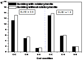
![]() ;
; ![]() =10,
=10, ![]() , and
, and ![]() =
= ![]() with
with ![]() =50
=50

Fig. 4. Comparisons between critical loads of out-of- plane buckling parameter ![]() ;
; ![]() =10,
=10, ![]() , and
, and ![]() =
=![]() with
with ![]() =100
=100
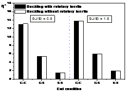
Fig. 5. Comparisons between critical loads of out-of- plane buckling parameter ![]() ;
; ![]() =10,
=10, ![]() , and
, and ![]() =
=![]() with
with ![]() =1000
=1000
6. Conclusions
The DQM is used to analyze the out-of-plane buckling of curved beams including the effect of rotatory inertia under uniformly distributed radial loads. The critical loads are calculated for the beams, and results are compared with existing exact solutions where available. The present approach gives excellent results for the cases treated using only ten discrete points. New results are given for two sets of boundary conditions not considered by previous researchers: Both ends are clamped-clamped and simply-simply supported.
The present approach gives the followings:
1) The results by the DQM give the mathematical precision compared with the exact solutions by others (less than 0.3%).
2) The variation of the rotatory inertia ratio ![]() affects the buckling behavior more significantly than the variation of the stiffness parameter
affects the buckling behavior more significantly than the variation of the stiffness parameter ![]() .
.
3)The critical value of buckling parameters including the effects of rotatory inertial affects the beam behavior more importantly than neglecting the effects of rotatory inertial.
4)Variations of the opening angle, boundary condition, stiffness parameter, and rotatory inertia are import roles in the buckling behavior of curved beams.
5) Diversity of new results according to the opening angles, boundary conditions, stiffness parameter, and rotatory inertia is also suggested. Those results can be used in the comparisons with other numerical solutions or with experimental test data.
References
[1] M. Ojalvo, E. Demuts, F. Tokarz, "Out-of-plane buckling of curved members", J. Struct. Dvi., ASCE, vol. 95, pp. 2305-2316, 1969.
[2] V. Z. Vlasov, Thin walled elastic beams, 2nd edn, English Translation, National Science Foundation, Washington, D.C., 1961.
[3] J. A. Cheney, "Bending and buckling of thin-walled open-section rings", J. Engng Mech. Div., ASCE, vol. 89, pp. 17-44, 1963.
[4] C. H. Yoo, P. A. Pfeiffer, "Elastic stability of curved members", J. Struct. Engng, ASCE, vol. 109, pp. 2922-2940, 1983.
DOI: http://dx.doi.org/10.1061/(ASCE)0733-9445(1983)109 :12(2922)
[5] J. P. Papangelis, N. S. Trahair, "Flexural -torsional buckling of arches", J. Struct. Engng, ASCE, vol. 113, pp. 889-906, 1987.
DOI: http://dx.doi.org/10.1061/(ASCE)0733-9445(1987)113 :4(889)
[6] S. P. Timoshenko, J. M. Gere, Theory of elastic stability, 2nd edn, McGraw-Hill, New York, 1961.
[7] N. S. Trahair, J. P. Papangelis, "Flexural -torsional buckling of monosymmetric arches", J. Struct. Engng, ASCE, vol. 113, pp. 2271-2288, 1987.
DOI: http://dx.doi.org/10.1061/(ASCE)0733-9445(1987)113: 10(2271)
[8] Y. B. Yang, S. R. Kuo, "Static stability of curved thin-walled beams", J. Struct. Engng, ASCE, vol. 112, pp. 821-841, 1986.
DOI: http://dx.doi.org/10.1061/(ASCE)0733-9399(1986)112: 8(821)
[9] S. R. Kuo, Y. B. Yang, "New theory on buckling of curved beams", J. Engng Mech., ASCE, vol. 117, pp. 1698-1717, 1991.
[10] Y. J. Kang, C. H. Yoo, "Thin-walled curved beams II: Analytical solutions for buckling of arches", J. Struct. Engng, ASCE, vol. 120, pp. 2102-2125, 1994.
DOI: http://dx.doi.org/10.1061/(ASCE)0733-9399(1994)120: 10(2102)
[11] Y. L. Pi, J. P. Papangelis, N. S. Trahair, "Prebuckling deformations and flexural-torsional buckling of arches", J. Struct. Engng, ASCE, vol. 121, pp. 1313-1322, 1995.
DOI: http://dx.doi.org/10.1061/(ASCE)0733-9445(1995)121: 9(1313)
[12] K. Kang, J. Han, "Buckling analysis of arches using DQM", J. KIIS., vol. 12, pp. 220-229, 1997.
[13] R. E. Bellman, J. Casti, "Differential quadrature and long-term integration", J. Math. Anal. Applic., vol. 34, pp. 235-238, 1971.
DOI: http://dx.doi.org/10.1016/0022-247X(71)90110-7
[14] C. P. Tan, S. Shore, "Dynamic response of a horizontally curved bridge", J. Struct. Div. ASCE, Vol 94, pp. 761-781, 1968.
[15] T. Wah, "Buckling of thin circular rings under uniform pressure", Int. J. Solids Struct., vol. 3, pp. 967-974, 1967.
DOI: http://dx.doi.org/10.1016/0020-7683(67)90022-4
[16] S. K. Jang, C. W. Bert, A. G. Striz, "Application of differential quadrature to static analysis of structural components", Int. J. Numer. Mech. Engng, vol. 28, pp. 561-577, 1989.
DOI: http://dx.doi.org/10.1002/nme.1620280306
[17] K. Kang, Y. Kim, "In-plane vibration analysis of asymmetric curved beams using DQM", J. KAIS., vol. 11, pp. 2734-274, 2010.
DOI: http://dx.doi.org/10.5762/kais.2010.11.8.2734
[18] K. Kang, C. Park, "In-plane buckling analysis of asymmetric curved beams using DQM", J. KAIS., vol. 141, pp. 4706-4712, 2013.
DOI: http://dx.doi.org/10.5762/kais.2013.14.10.4706
|
Ki-Jun Kang [Regular Member] |
|
|
|
•Feb. 1984 : Chungnam National University, Dept. of Mechanical Engineering (B.S), •Dec. 1989 : San Jose State University, Dept. of Mechanical Engineering (M.S) •Dec. 1995 : University of Oklahoma, Dept. of Mechanical Engineering (Ph.D) |
|
•Mar. 1997 ~ the present : Dept. of Mechanical Engineering, Hoseo University, Professor
<Areas studied> Structural and Numerical Analysis, Buckling, Vibration |
|